2021-05-23

I was reading hacker news aimlessly on the couch, as one does when home alone on a Sunday afternoon, when I came across this post. Printable circuits with a cheap inkjet printer? How exciting! Think of the possibilities!
I shared the post with a few of my friends. Jason got back to me, and we started thinking about what we could do with this kind of tech.
Soon, the idea occurred to me: how about creating a little toy paper fortune-teller (or cootie catcher) that completes a circuit. Like, it could turn on lights or make sounds, depending on how the fortune-teller was folded. A bonus point about making a simple paper toy: I am getting married in about a year, and wanted to have some sort of interactive art thing at my wedding. With a hacked circuit printer, I could create a viable electronic at the scale of a wedding while staying on budget. Guests could fold their own cootie catcher, add LEDs and a battery, and then play games with each other at cocktail hour. How fun!
But, would it even work? I Googled around a bit and came to learn that all the components of this project are pretty cheap. I ordered a circuit ink pen and some electronics, and moved on to thinking about the design.
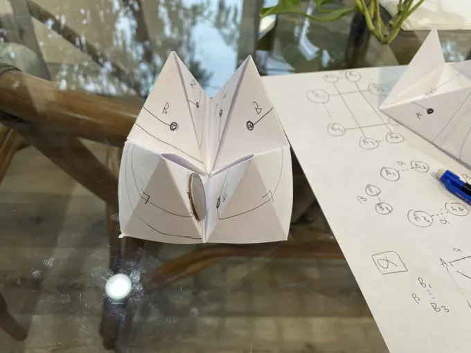
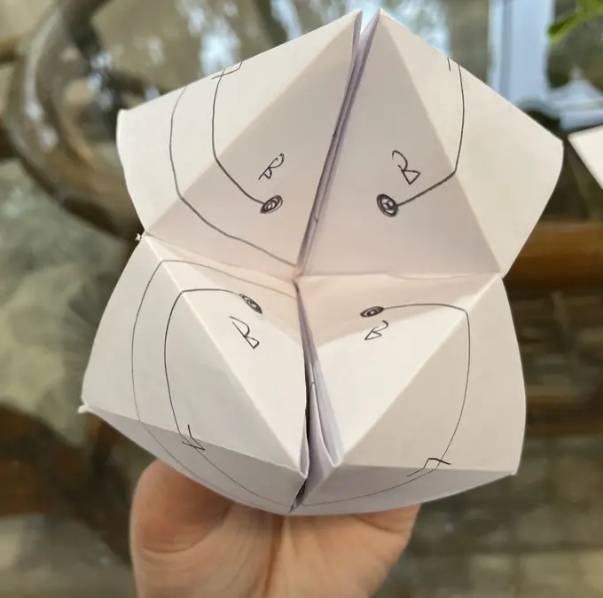
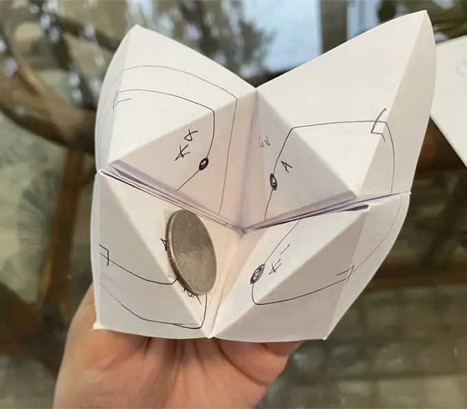
I folded myself a fortune-teller and began thinking of how the circuit would work. Here was my prototype v0.0:
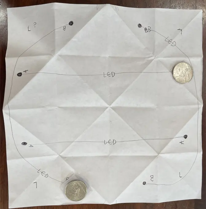
I used quarters here in place of coin-sized batteries. The lines represent paths with conductive ink, and the black dots should become contact points for the batteries when folded.
As you can see, when you press the "B" dots together, two outside LEDs would turn on.
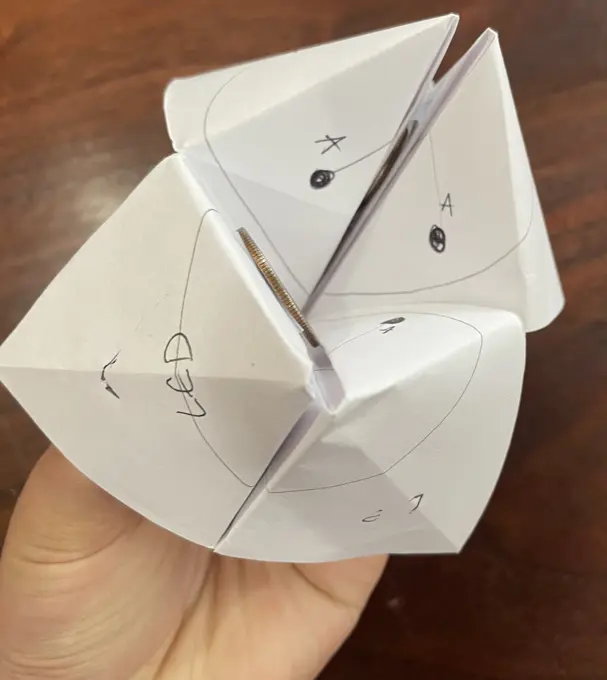
When you press the "A" dots together, light would shine through the center of the fortune teller.
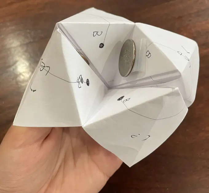
This seems fine, but I imagine using two batteries could get pricey at the scale of ~200 guests for our wedding (not to mention, wasteful). How could I create the catcher such that it used only one battery?
I unfolded the fortune-teller and tried to model the connections more abstractly as a graph. The dotted lines below represent folded connections, whereas solid lines would be silver-ink connections in paper.
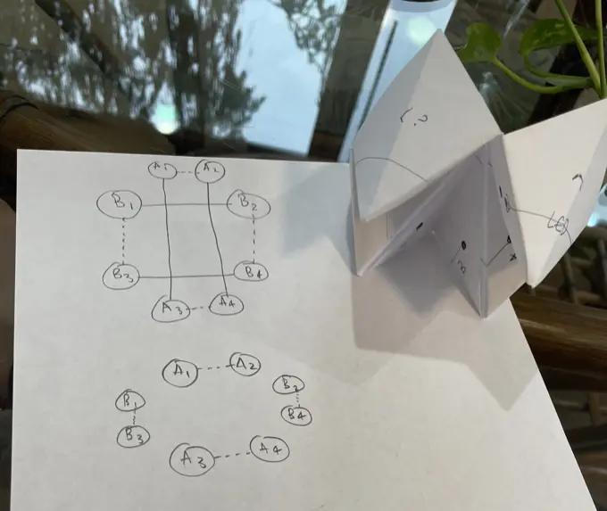
I noticed that the dotted lines here weren't telling the whole picture: Each line is associated with a connection "mode." While alpha was connected, beta wasn't, and visa versa.
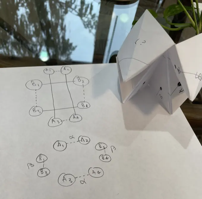
The aspiring math teacher in me wants to ask: How would you draw the circuit? It was fun for me to solve, and if you've read this far, I imagine it would be fun for you too.
So, to come up with a more efficient solution, I tried to sketch out a consistent solid line graph for each mode. After one incorrect attempt, I figured out a configuration that would complete a full circuit for each mode with only one battery.
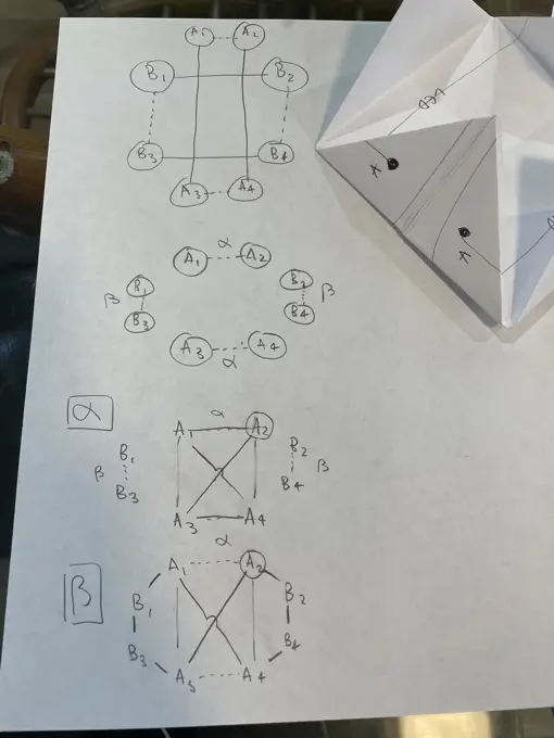
(the trick was to cross the "A" connections)
This seemed good so far. However, for this to work, my graph needs to be planar. Can I fit the one-battery circuit on one page?
The answer was "yes!" With another sketch, I had v0.1 of my design:
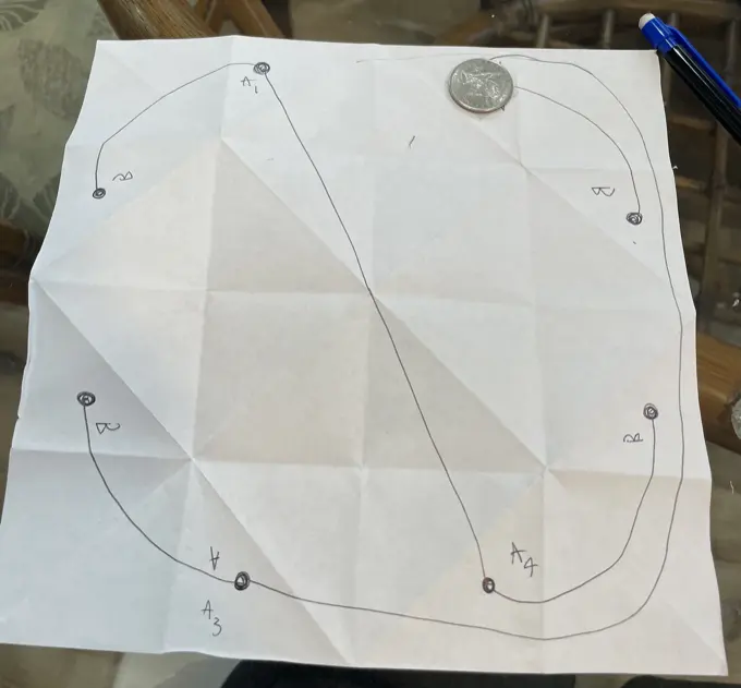
Folded together, the circuit would turn on two outer LEDs when "A" was pressed together, and the two other LEDs when "B" was pressed.
I told Jason all this, and he asked a good question: Would the silver ink connections remain robust during folding? I did a quick inspect of every crease, and to my best estimation, it seems to be the case! – no short circuits.
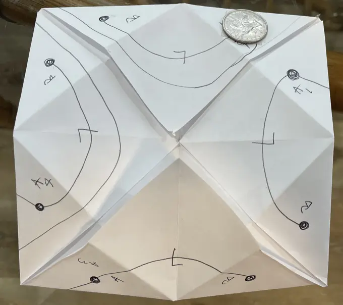
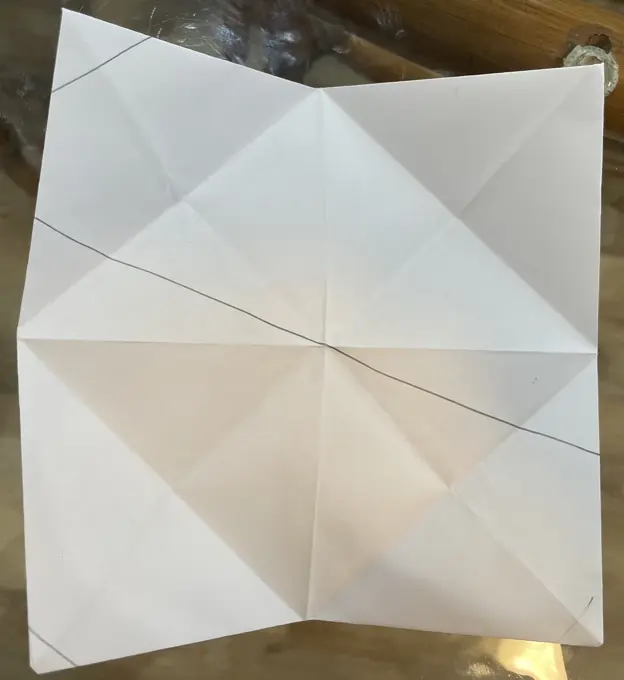
Later, Jason would point out something that would require an adjustment in my design. In v0.0, I was relying on each battery making contact with the silver ink. However, in v0.1, as displayed in the picture, I need to rely on a different mechanism to complete the circuit. The cootie catcher needs to be folded in a way such that each face of the battery makes contact with the silver ink. All this means is that the position for my battery needs to be re-worked; it's not a total deal breaker.
I'm sure I'll run into other issues that I can't anticipate. I feel pretty good about being able to sort those out as I complete v1.x of this prototype, once my supplies arrive.
While I wait, I can't help but dream of other possibilities based on this simple experience.
It occurs to me that the kind of folks who find origami satisfying probably overlap quite a bit with the folks who find circuit building satisfying. The prospect of accessible printable circuits offers a unique opportunity to cater to both audiences at once.
To generalize here, what if I could create a series of novel, origami-based puzzles? Like, you get a piece of paper with normal ink lines to indicate folds. A conductive ink layer interspersed with LEDs offers the origamist clues on the fold order, guiding them to make the origami shape by turning on lights.
Imagine creating a program to model circuits that live on folded paper. Nodes could be polygons from folds with various types of circuitry. Different kinds of edges might express relationships based on neighborship on a plane or fold. Maybe we could speed up writing such a program by extending existing PCB-design software. But, can it handle the topological challenge?
Jason had fascinating ideas along the lines of different kinds of circuit patterns. For one, he suggested the possibility of using photoresistor and LED as a new type of interactive connection similar to a fold. In this scheme, a circuit is complete when the active LED is near the photoresistor and broken when they are apart. He had a few other ideas of other types of circuits that could be used to make new "edges" or interactive, foldable connections.
Jason's current area of exploration: Paper planes.
What other kind of cool contraptions could we make?